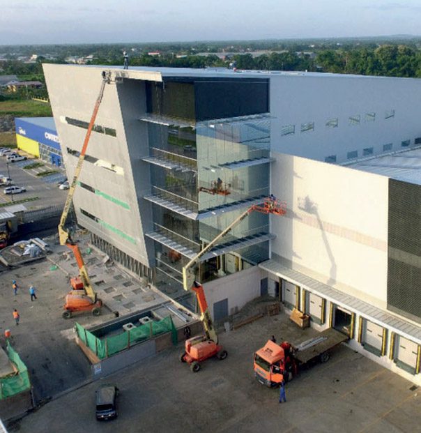
Insulated Sandwich Panels for Cold Rooms
Product manufactured by

- Cold-room panels | Master Frigo
- Technical specifications
- ASSEMBLY AND ERECTION
- Finishes and colour chart
- Downloads
- Handling and maintenance
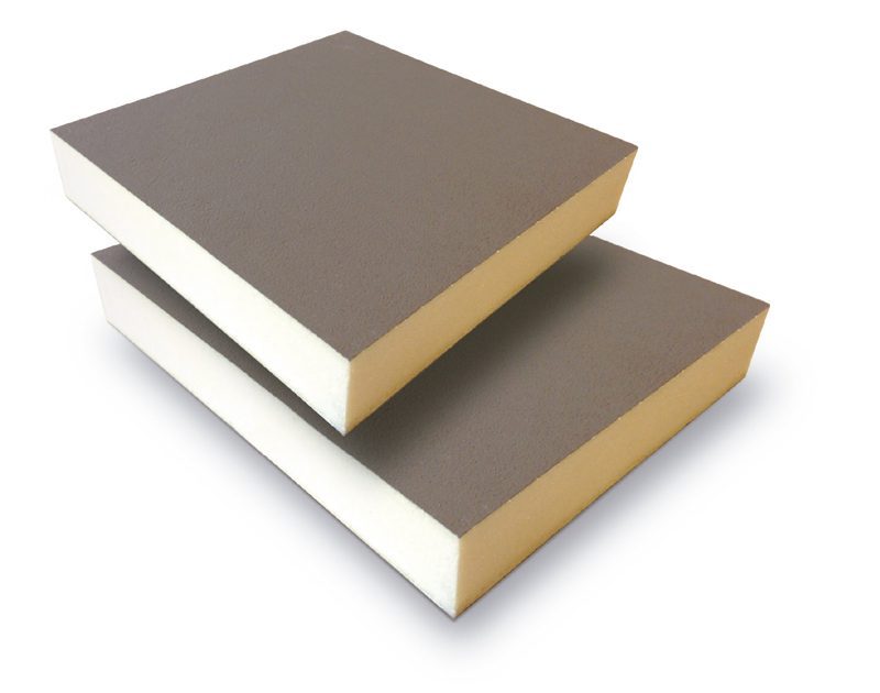
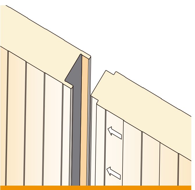
MASTER-FRIGO panels are continuous production line prefabricated panels, and are composed of two faces of prepainted galvanized steel, bonded to a core of rigid polyurethane (PUR) or polyisocyanurate (PIR) foam, forming a sandwich type element with tongue and groove joints.
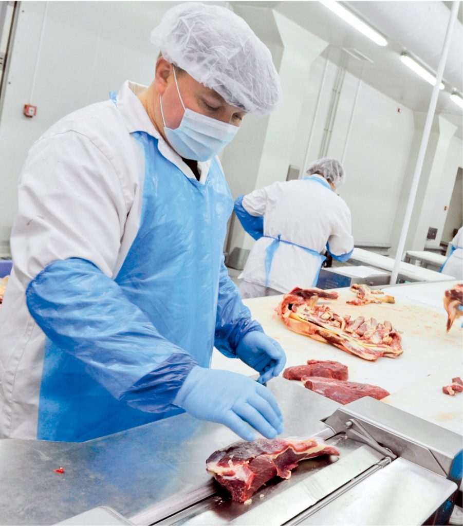
MASTER-FRIGO panels are specially designed for use in all types of projects related to the agri-food industry, from transport, handling and storage through to the freezing and deep-freezing of foods.
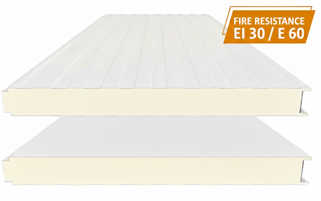
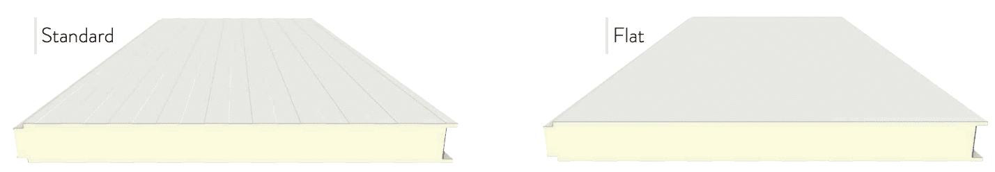
MASTERPANEL offers various different configurations according to the project they will be used in, and it comes in five different thicknesses, two outer ribbing designs and two inner ribbing designs, as well as a wide range of available colours. Additionally, MASTERPANEL also offers the option of panels manufactured with PIR (polyisocyanurate) self-extinguishing foam with a B-s1, d0 certification under Euroclasses (UNE-EN 13501).
Technical specifications
| Panel thickness | 60, 80, 100, 120, 150 mm. |
| Cover Width | 1.000mm |
| Length | Up to 16.000 mm. (max. recommended 9,000 mm) |
| Field of application | Cold room |
| Outer face thickness: | 0,4 / 0,5 / 0,6 / 0,7 mm |
| Inner face thickness: | 0,4 / 0,5 / 0,6 / 0,7 mm |
| Coatings (see section on Finishes): |
|
| Outer ribbing | Standard / Flat |
| Inner ribbing | Standard / Flat |
| Core type |
|
| Core Density | 40kg/m³ |
| Thermal Conductivity | 0,021 W/m K |
| Tensile strength | >0,060Mpa |
| Compressive strength | >0,100Mpa |
| Flexural strength | >0,100Mpa |
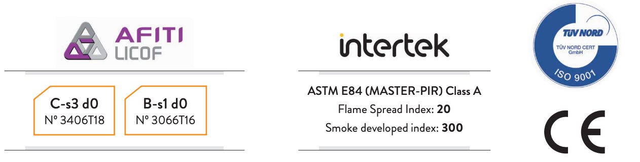
| Reaction to fire | Cs3d0 / Bs1d0 |
| Fire resitance | EI 30 / E 60 (Thickness ≥ 100mm) |
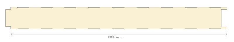
Dimensions in mm.
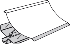
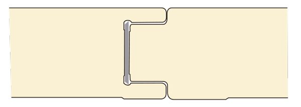
Joint detail.
| Panel thickness | Weight | Thermal transmittance (U-Value) | Thermal resistance (R-Value) | ||
| mm | kg/m2 | w/m2 k | kcal/m2 h ºC | m2k/w | Hr f² °F/BTU |
| 60 | 9,94 | 0,36 | 0,31 | 2,76 | 15,66 |
| 80 | 10,72 | 0,27 | 0,23 | 3,75 | 21,26 |
| 100 | 11,50 | 0,21 | 0,18 | 4,71 | 26,73 |
| 120 | 12,28 | 0,18 | 0,15 | 5,67 | 32,15 |
| 150 | 13,45 | 0,14 | 0,12 | 7,09 | 40,21 |
Calculations according to EN14509, measuring the surface resistance according to horizontal flow and omitting the influence of the profiled faces. Losses in bolted connections must be calculated by the designer.
FUNCTIONS AND BENEFITS OF MASTER-FRIGO PANELS
- Aesthetically appealing
- Efficient thermal insulation capacity
- High mechanical strength
- Exceptional dimensional stability
- Watertight against water vapor
- Resistant to aggressive environments
- A versatile material that allows any configuration
- Quick to install and easy to maintain (easy to clean)
- Easily removable and can be reused
- Made-to-measure, avoids waste
- Made with recyclable materials
REACTION TO FIRE
Permissible overloads (kg/m2)
| Panel thickness mm |
(L) Span distance in cm. Calculations made on 0.50 mm / 0.50 mm panel. | ||||||||||||
| 150 | 175 | 200 | 225 | 250 | 275 | 300 | 325 | 350 | 375 | 400 | 450 | 500 | |
| 60 | 413 | 332 | 272 | 225 | 188 | 159 | 135 | 115 | 99 | 85 | 74 | 57 | |
| 80 | 471 | 391 | 328 | 278 | 237 | 204 | 176 | 153 | 133 | 117 | 91 | ||
| 100 | 433 | 371 | 319 | 277 | 241 | 211 | 186 | 164 | 129 | 103 | |||
| 120 | 466 | 404 | 352 | 309 | 272 | 241 | 214 | 171 | 138 | ||||
| 150 | 533 | 469 | 415 | 368 | 328 | 249 | 237 | 194 | |||||
Evenly distributed pressure overload for 1 span (2 supports).
Calculated for a Service Limit State of deformations L / 200. According to EN14509
Overloads not factored. The designer must carry out the calculations in accordance with the applicable regulations.
ASSEMBLY AND ERECTION OF COLD ROOMS
Basic assembly instructions:
- The ground on which the sandwich panels are to be set up should be completely flat, clean and smooth.
- Once the panels are installed, the verticality (walls) and horizontality (ceilings and roofs) should be checked, and any deviations corrected.
- The system of vertical jointing between panels is effected by pressure on the tongue and groove joint, with the panels being brought flush to each other.
- The wall–ceiling junction should be carried out strictly following the instructions provided (see technical details on page 88), with special attention being paid to cuts that are made, when these may be necessary, to create the junction.
- When the joint between panels does not by itself have sufficient capacity to prevent the formation of condensation or ice, a sealant is applied in that area; this could be silicone (for air and water tightness), butyl (for water vapour tightness) or foam injected on site (to reduce the thermal bridge between the panels).
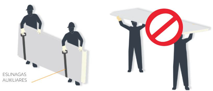
- The fixing of roof panels attached to building structures should be performed using connector rods or guy wires. The building structure must be designed to withstand both its usual loads and those due to the weight of the panels themselves.
- The maximum length of the vertical or horizontal spans, as well as the maximum permissible loads on the panels, should comply with those specified (see table on admissible loads page 39) for the type of panel to be used.
- Refrigerating equipment and accessories must not be directly hung from the panels, but require a separate support system.
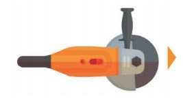
- Avoid the use of cutting discs, as these may produce metal shavings which can stick to the panel surfaces and cause oxidation problems. If cutting discs must be used, ensure the complete removal of all metal shavings.
- Check that appropriate screws for the required structure are used.
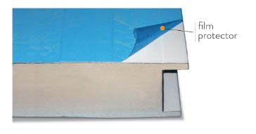
- Remove the protective plastic film from the panels.
- Ensure that any possible scratches that may occur on the outer face are correctly repaired.
- Check that individual points are properly sealed.
MAINTENANCE GUIDELINES FOR COLD ROOM
- The condition and tension of the ceiling fastenings tensors must be checked as well as cleaned every six months.
- The panel surfaces can be washed with a mixture of tap water and a neutral agent, then rinsed with running water and dried.
- Check the water collection channels once a year, ensuring that they are clean and in good condition.
- Check the condition of the sealing elements once a year.

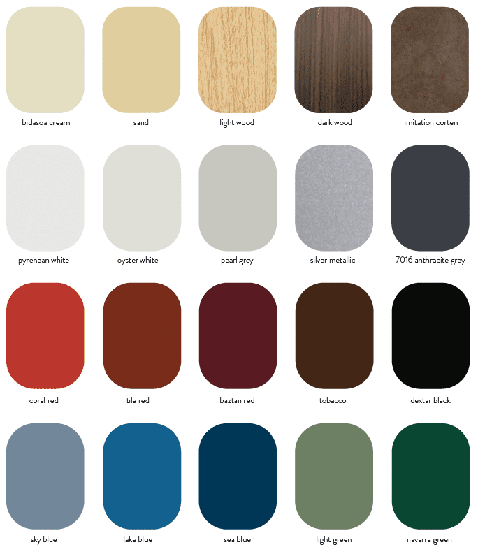
- Colours in this catalogue are approximate.
- Possibility of manufacturing in other colours on request.
In order to choose the right prepainted finish for each use, the planner responsible for the design of the project must take into account both the incidence of UV rays and the exposure to corrosive environments of the building or project.
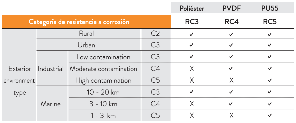
- Corrosion resistance of the paint system To determine the corrosion resistance of a paint system, it is subjected to the salt spray test. This test evaluates the appearance of corrosion after a number of hours in a saline mist chamber. The results provide each paint scheme with an RC corrosion resistance value, from RC1 to RC5, with RC1 being the lowest value. This means that those RC3 rated paint schemes have shown their suitability for environments rated C3 or lower.
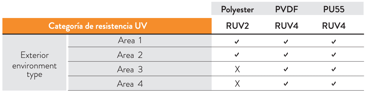
- Resistance to UV radiation of the paint system To determine the UV resistance of a paint system, it is subjected to the QUV accelerated aging test. This test evaluates the loss of gloss and colour over time due to UV rays. The results provide each paint scheme with a UV resistance value RUV, from RUV1 to RUV4, with RUV1 being the lowest value.
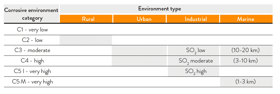
- Classification of environments DESCRIPTION
DESCRIPTION OF CORROSIVE CATEGORIES FOR EXTERNAL ENVIRONMENTS
C2 Low: Areas with low level of contamination. Mainly rural or industrial areas without incidence by sulphur dioxide.
C3 Moderate: Urban and industrial areas with low sulphur dioxide (SO2) pollution and coastal areas with low salinity (from 10 km to 20 km from the sea).
C4 High: Industrial areas with moderate contamination by sulphur dioxide (SO2) and coastal areas with moderate salinity (from 3 km to 10 km from the sea).
C5 I Very high: Industrial areas with very aggressive atmospheres and high contamination by sulphur dioxide (SO2)
C5 M Very high: Coastal and maritime areas with high salinity (from 1 km to 3 km from the sea).
DESCRIPTION OF THE CATEGORIES OF UV RESISTANCE FOR EXTERNAL ENVIRONMENTS
Area 1: Areas not exposed to UV radiation. Indoor use without any radiation.
Area 2: Areas with low exposure to UV radiation or without special colour maintenance requirements.
Area 3: Areas with moderate exposure to UV radiation.
Area 4: Areas with high exposure to UV radiation or with special colour maintenance requirements.
Choice of finishes for different environments
Once the category of the environment is known, the person responsible for the design must decide on the painting system:
1) The suitable paint system needs to be determined in terms of corrosion. The following table can be used as a guide.
2) The suitable paint system in terms of UV radiation have to be determined. The following table can be used as a guide.
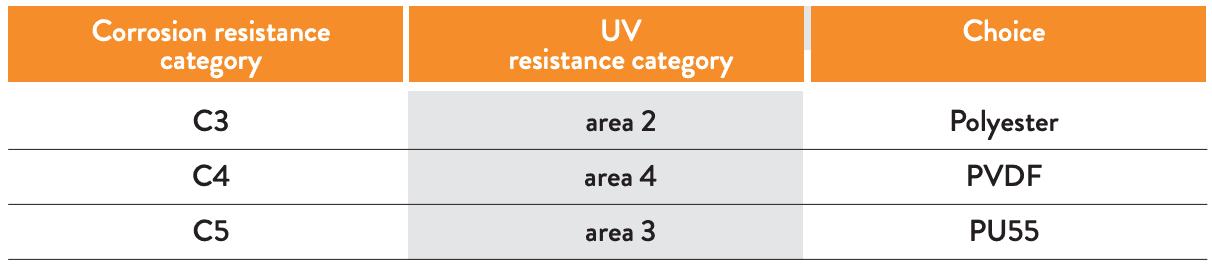
3) A suitable paint system should be chosen in terms of both corrosion resistance and UV resistance. The following cases can be used as a guide.
The data stated in the tables is informative and does not constitute a guarantee of the material. You should contact Masterpanel about any applications which require a guarantee for the steel in the panels.
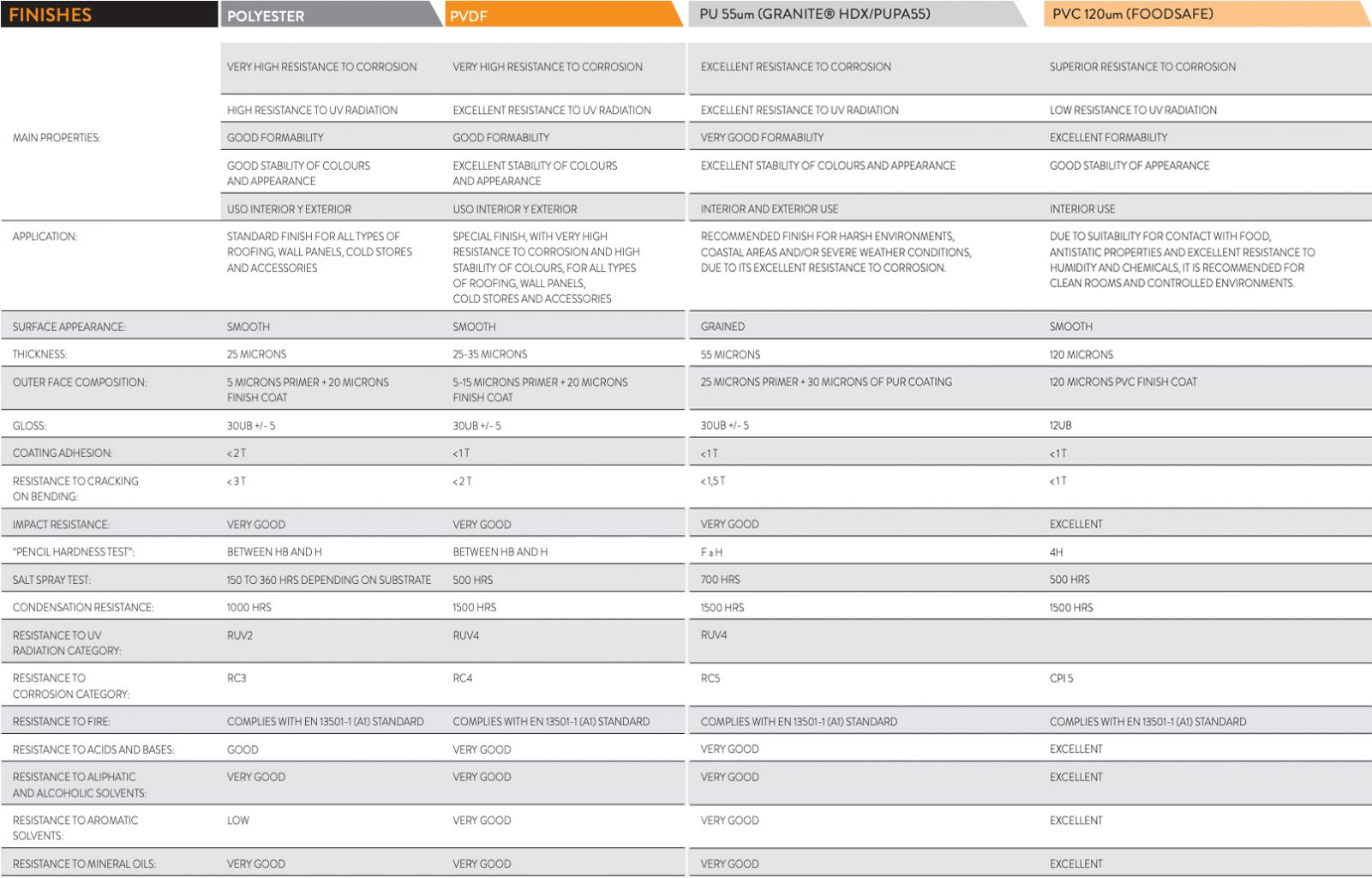
Standard finish: Polyester 25 um. Other finishes available on request. Guide values to be taken as a reference. Consult for guarantees.
In order to provide you with information about this product, we offer you all the documentation concerning Master-Frigo / Cold room.


MasterPanel offers our clients a technical department to support your designers and Project Management. Our building system section provides support from the initial concept of the project to the installation and subsequent maintenance.
- Proposals for appropriate technical solutions for each project.
- Providing support regarding the cutting, quantifications of the panels and necessary accessories.
- Support and technical information for the training of fitters.
- We provide plans and sketches of the most common technical details.
- Technical support in the correct installation of our panels, forming a team with the Project Management
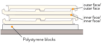
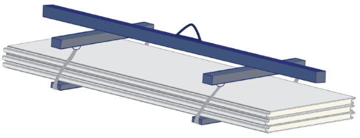
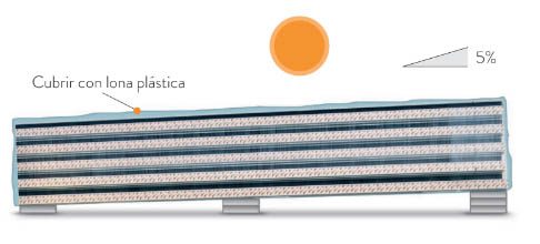
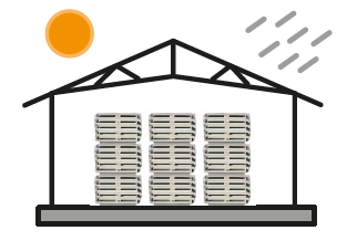
- Panels must always be transported on flatbed vehicles.
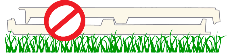
- Panels will always be packed with polystyrene blocks at the base to avoid damage.
- Panel stacks should never exceed 2.60 m. high (including polystyrene blocks, accessories, cover caps, trims, etc).